Automation modules.
Once we have all shutter wires (2 per motors, 2 per buttons = 4 wires per shutter) then I have created 2 PCBs, one is managing button states, the other one is driving motors.
Button manager
Information delivered by buttons are using the main line voltage : 230V. So this module should convert this to a TTL (0 – 5V) information. To be in a safe environment, I used photo coupler. Here is schematic for one button :
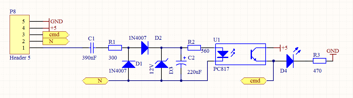
230V information come from shutter button (Up for example) and is connected to capacitor C1. Then using resistor, zener diode and normal diode voltage is dropped down to 12V this is filtered by capacitor C2. This voltage is then driving a photo coupler diode.
Photo transitor of the photo coupler is driving a LED at 5V level, it is also giving the switch information.
When 230V is present, then cmd is set to 5V, otherwise, cmd is set to 0V.
As I have 8 shutters, I need to have 2 times this schematic per button (Up/Down), so there is 16 times this schematic :

From this schematic I created PCB like this one :
As you can see on the PCB and schematic, there is P3, P101, P102… points. This points are there because this board will be associated with the motors driving board like a sandwish.
On connector P5 we have all TTL signal of each shutter button.
Motor drivers
Again, motor are using 230V and I would like to work with TTL level (5V) so I should do an adaptation.
I have chosen to use relay because I have 30 of them.
Here is the schematic to drive one motor :
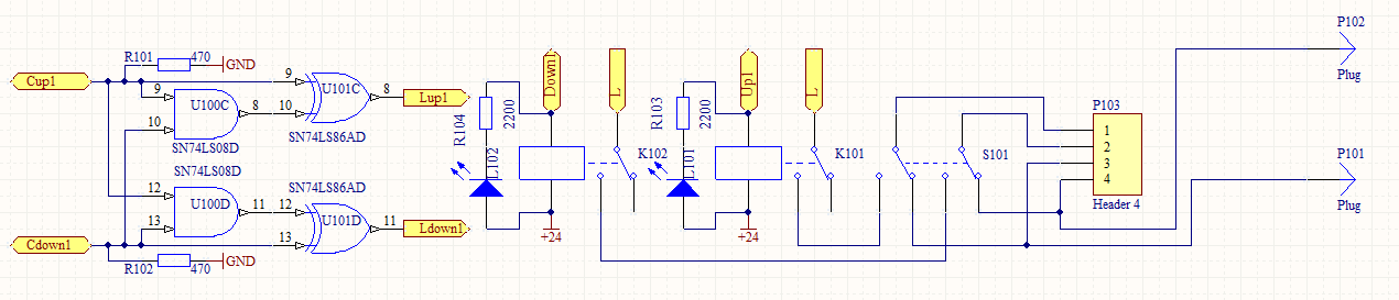
Motor (Up and Down) and corresponding button (Up and Down) are connected to connector P103. You can see switch S101, this switch is here only to short automation, when the switch is in position like shown on the schematic, there is no automation, this is like if the shutter button are directly connected to motor.
This S101 is optional, I used it in the case one shutter should not be centralized.
TTL command is coming via Cup1 and Cdown1, then there is logic gates to be sure both relay won’t be activated at the same time (Up and Down at the same time, not sure motor will appreciate…) Even if this can be handled by software, I prefer to implement it also as hardware. Then signal Lup1 and Ldown1 are driving relay via an ULN2803 not shown in the schematic. There is also LED to know the relay state.
The use of ULN2803 let me use a different voltage to power relays, I use 24V, but it can be another voltage (5, 12…) Then resistor values for LED should be changed accordingly.
In this schematic we cannot also see diode protection on the relay coil.
The complete schematic is :

On this schematic you can see 8 motor drivers.
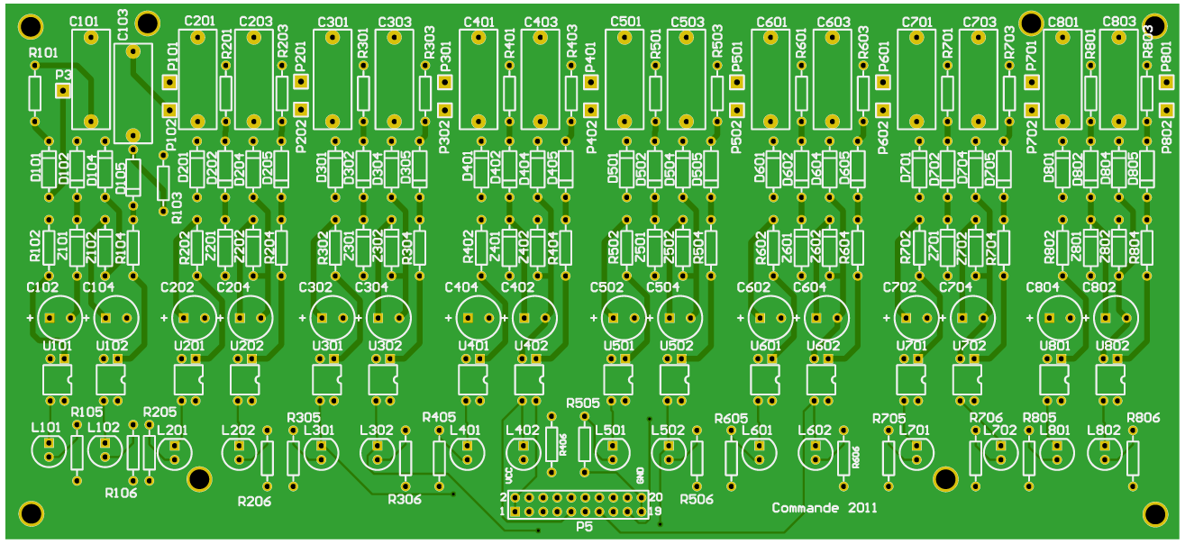
The PCB is the following :

P103, P203… are where motor and switch button are connected (4 wires)
P1 is main power Line and Neutral
P3, P101, P102… are connected to the button manager board
P2 is used as power supply relay, mine are using 24 VDC
P4 is the connector used to drive relays with TTL levels 5V
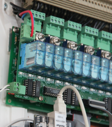
Here you can see both boards :
Main shutter switch
With the 2 boards, I am able to get shutter buttons information and set motor up and down. But I also need a main button that will be used as a general switch to drive all shutters.
So I have created a small PCB that is handling this button. I used the same thing as for button manager. Here is the schematic used :
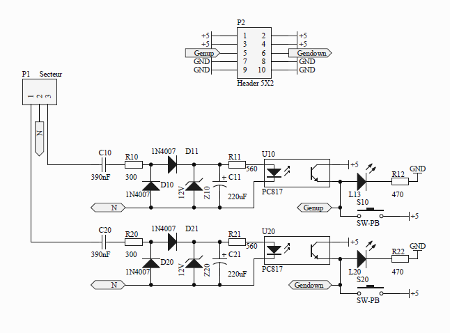
As button is using 230V I use the same thing to get TTL levels.
Here is the PCB :
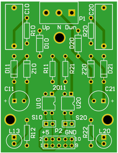
P1 is connected to main button (Up and Down) and also to neutral.
P2 is TTL levels (5V) reflecting button state.
With these 3 PCBs, I can then make the automation using either a microcontroller like PIC from Microship, or use an Arduino, or use a Raspberry Pi, or ….
At first stage I used an Arduino because this was the easiest way for me, and also because Raspberry Pi was not available yet !